Reading welding symbols is very important at several levels of an organization. A welder needs to be able to interpret welding symbols to insure he puts down the right kind of weld, that he prepares the joint properly, that he places the weld in the right spot, right sequence, right dimension, etc. A design engineer needs to know the symbols to communicate this clearly to the welders and supervisors. A project manager will need to know this when bidding a job. The welding symbols will tell him or her the exact amount of weld metal required, which can in turn be used to estimate that total amount of filler metal that is required per part or per job.
If you have not read “9 Basic Steps to Reading Welding Symbols” it may be worth taking a look before continuing with this post. The “9 Basic Steps to Reading Welding Symbols” focuses on fillet welds, but goes thru the basics of the welding symbol (arrow, reference line, and location of welds) which is not covered here.
Unlike fillet welds where there is no variation, there are many different types of groove welds. These are determined by the joint geometry. The following 8 steps will make it easier to interpret welding symbols for groove welds.
1. Determine the type of joint and joint preparation needed.
The American Welding Society, in its publication AWS A2.4:2007 – Standard Symbols for Welding, Brazing, and Nondestructive Examination (current version is AWS A2.4:2012) provides the different types of groove joints which can be single or double. Single being on one side of the joint only and double being both sides of the joint. The welding symbols for the different groove joints are:
• Square Groove
• Scarf
• V-Groove
• Bevel Groove
• J-Groove
• U-Groove
• Flare V-Groove
• Flare Bevel Groove
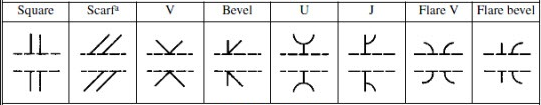
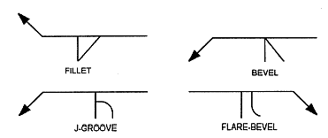
Groove Weld Symbols
The welding symbols for groove welds will go on the reference lines in the same manner as fillet weld symbols as shown below.
Groove weld symbols are placed on the reference line in similar fashion to fillet weld symbols
2. Determine the root opening.
The root opening will be show inside the groove type symbol as shown on the image below. This is the dimension of the separation between the two pieces. If no dimension is shown there is no gap between the parts. Having a “0” is also acceptable.
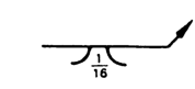
This diagram calls for a flared-bevel on the arrow side having a root opening (gap) of 1/16.
3. Determine the groove angle.
The groove angle will be above or below (depending on whether it is arrow side or other side) the root dimension and will be expressed in degrees.
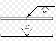
60 degree groove angle
4. Determine the root radii and root face dimensions (for J-Groove and U-Groove welds only).
These dimensions will need to be specified in one of two ways:
A. With a cross section drawing of the joint showing dimensions.
B. Notes on the tail of the welding symbol as shown below where SEC A-A references another document that contains the details of the joint.
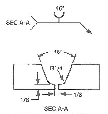
Radius of joint and face dimension (land) are shown on a diagram referenced by a note on the tail of the symbol
5. Determine the depth of the groove.
The depth of groove preparation will be shown to the left side of the groove weld symbol. The diagram below shows a groove with a joint preparation depth of 3/8”.
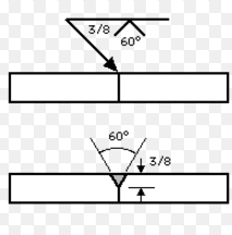
This welding symbols shows a groove angle of 60 degrees and a depth of 3/8.
6. Determine the weld size.
The size of the weld is the effective throat on a groove weld. This includes the depth of groove and the additional penetration into the root. The size of weld will be shown to the left of the groove symbol in parenthesis. If there is no number in parenthesis then the size of the weld should not be less than the groove depth.
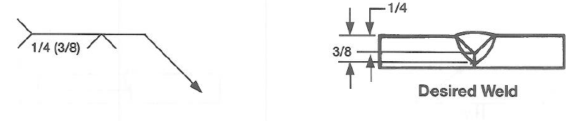
Welding symbol showing both groove depth and weld size.
7. Determine the finish contour.
As with fillet welds we can have three types of finish contour.
A. Flat/Flush
B. Convex
C. Concave
These are depicted by the symbols in the images shown below.
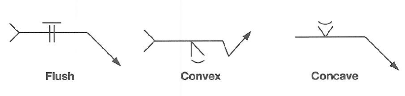
There are three types of contours for welds
8. Determine the finishing method.
The welding symbol can also tell you how the contour is to be achieved. For example, the requirement may be a flat contour by grinding. AWS A2.4:2007 – Standard Symbols for Welding, Brazing, and Nondestructive Examination specifies finishing methods with a 7th being “unspecified method:”
C – Chipping
G – Grinding
H- Hammering
M – Machining
P – Planishing
R – Rolling
U – Unspecified
These notations will appear above (or below) the contour symbol as seen below where a flat contour is achieved by grinding.
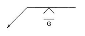
The symbol calls for a groove weld with a flat finish achieved by grinding.
9. Determine the side of the joint to be prepared when the drawing calls for a single bevel.
In the case of a bevel, J-groove, and flare bevel the welding symbol will tell you which side to prepare (bevel) by having a “broken” arrow as seen below. Whenever you see this broken arrow you know that the side to be prepared is the side to which the arrow points.
A broken arrow will point to the side of the joint that needs to be beveled.
By having read thru these 9 simple steps you already know more about welding symbols than 95% of the people in the welding industry. Training for welding symbols readings can be done in a couple of hours if you stick to the basic, but can be as long as 20+ hours if you go extreme detail. The information above should get you going but it is not exhaustive.
Do you need to become fluent interpreting and writing welding symbols? Are you preparing for the CWI or CWS exam? Are you looking to develop welding symbols tests for your employees or students? Regardless of your reasons for learning welding symbols the Welding Symbols Training manual will have help you learn this language easily and quickly. Learn more about this resource by clicking here.
Source: AWS A2.4:2007 – Standard Symbols for Welding, Brazing, and Nondestructive Examination
Really most informative and much more help for learners.
good explanation
great book
very interested for my studends
Thanks
A very informative and helpful blog for the learners who are ambitious to become true welding professionals.
Really good
Do you have any information on speeds, feeds depending on the wire size. I will be very interested to know. I am working with fabrication suppliers but this is not my strength.
Hello Chris, are you referring to wire feed speeds for different wire sizes? If this is what you are looking for you can go to the wire manufacturer’s website and they provide operating ranges for their wires.
Thank you . It was very informative.
4140, MIG weld
stacking with other carbon steels
Preheat to weld
cool slowly like in ashes over night?
Sounds like 41040 is used mostly for tooling.
Thanks for the information related to welding
Thanks
thanks. great