The majority of industrial equipment and welded structural components are subjected to repeated fluctuating loads. These loads are typically of magnitudes that are within the elastic region of the material and well below its yield strength. This means that any deformation of the structure caused by the applied stress will then return to its normal shape and size when the stress is removed. Examples of equipment and structures that are subject to fatigue loading include bridges, ships, cars, airplanes, drilling equipment, earthmoving equipment, pumps, oil rig platforms, trailer frames, etc.

Bridges are subjected to variable loads which place several of its members under tension and compression. It is not only the vehicles that create fluctuating stresses on the bridge, fluctuating winds also affect the fatigue life of the bridge.
Fatigue is the process by which damage is caused to a structure by the cumulative effects of repeated fluctuating loads. Think of a bridge and the millions of vehicles, from small cars to large trailers that go over it every day. Every time a vehicle goes through the bridge, there will be tensile and compressive stresses applied to the bridge members (girders and other components). These loads alone are significantly below the yield strength of the bridge components and weldments; however, through millions of cycles the structural components begin to debilitate and a crack may initiate. This crack will then propagate as a result of the repeated fluctuating loads until it grows to a critical size. Once this critical size is reached fracture occurs.
Crack propagation may be slow and may take months or even years to grow to a critical size. However, once the critical size is reached, the crack will grow at speeds of up to 7,000 feet per second [2134 m/s] resulting in catastrophic failure. This is why evaluation of existing structures is critical. When a flaw such as a crack is identified in a bridge during inspection a decision must be made. This decision is to run, repair, or replace. RUN means that the crack growth is such that the structure can still operate safely and no action is needed. REPAIR means that the structure is currently safe, but the expected crack growth rate is such that it will soon become dangerous and a repair must be made. Finally, REPLACE means that the entire structure has served its useful life and it is safer to replace it rather than try to repair it.
Welding codes such as AWS D1.1 Structural Welding Code (Steel) have strict requirements for welded components subjected to cyclic loading (repeated fluctuating loads). If you look through the code you’ll soon figure out that inspection is more stringent and allowances for welding discontinuities are much less when dealing with cyclically loaded components.
When structures subjected to fatigue loading are designed, there are many safety considerations taken by the engineer in charge. The design engineer must understand the type of loading, the mechanical properties of the building components, the type of welded joints, and many other factors. Fortunately, a lot of that work has been done through extensive testing of materials.
It is important to know that fatigue life is significantly reduced when we weld. This is due to several factors, some of which are:
- Introduction of tensile residual stresses
- Changes in geometry of the final welded component which create stress risers
- Introduction of mechanical notches (undercut, overlap, incomplete penetration, and other welding-induced discontinuities) which create even more dangerous stress risers
Clause 2 (Design of Welded Connections) of AWS D1.1 identifies different stress categories based on the geometry/shape of the final assembly after processes such as welding, drilling, punching, cutting, grinding, and others. These stress categories are then used by designers to estimate the fatigue life of welded components.
AWS D1.1 publishes S-N curves which tell designers the fatigue life, in number of cycles (N), they can expect out of a weldment in a specific stress category given the stress range (S) that will be experienced in service.
The stress range is the difference between the maximum stress applied and the minimum stress applied to the weldment. This can be fluctuating from a tensile load of 5Ksi to 1Ksi at which point the stress range would be 5 – 1 = 4Ksi. It can also fluctuate from a tensile stress to a compressive stress. For instance, a member can experience a tensile stress of 10ksi followed by a compressive stress of -5ksi. This would mean that the stress range is 10 – (-5) = 15ksi.
The larger the stress range the lower the fatigue life.
EXAMPLE: An engineer is designing a structure. The calculated stress range for this structure is 20ksi. The structural component being analyzed has been identified to fall within stress category D. What is the life (number of cycles) that can be expected out of this structure?
ANSWER: The first step is to compare the stress range (FSR = 20 ksi) with the threshold FTH value given in Table 2.5 of AWS D1.1 – Fatigue Stress Design Parameters. For stress category D the threshold FTH is 7 ksi [48 MPa]. If our stress range was below this value the structure would have an infinite life. However, since it is above we now need to use the formulas provided by the code.
Since FSR is greater FTH we have to use the formula provided by D1.1 to determine the number of cycles to failure. For stress category D we use Formula (2) given in Clause 2.16.2. Rearranging the parameters give us the following:
N = Cf / (Fsr)ᴲ
N = 22×10^8 / 20^3 = 275,000 cycles
We can also use the S-N curves provided by the code to do our estimates.
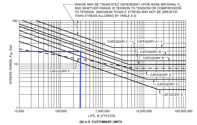
S-N curves are provided in the Design of Welded Connections clause (Clause 2) of AWS D1.1/D1.1M: Structural Welding Code – Steel and are useful for estimating fatigue life of welded components.
S-N curves are shown on log chart so be careful reading it. We identify the stress range of Fsr = 20Ksi on the vertical axis and draw a horizontal line to the right until we intersect the stress category D curve. We then draw a vertical line down to the number of cycles (N).
In this case the result is 300,000 cycles. As you can see we were off slightly that the true value of 275,000 cycles since we are using a graph. It is recommended that the graph be used just as quick reference. Always use the formulas when working on design.
275,000 cycles may seem like a lot, but not if the structure is a bridge or other component with a high number of experienced cycles per day. If the life is not acceptable the design engineer has three options:
- Find a way to decrease the stress range (i.e. limit the weight of vehicles allowed on the bridge)
- Redesign the structure to move it into a different stress category
- Both 1 & 2
As fabricators we must be very concerned with fatigue and understand why minimizing discontinuities is essential. As stated above, any time we weld we are decreasing the fatigue life of a structure. In addition to that, if we have discontinuities such as cracks or undercut the fatigue life is further reduced. Conservative design will assume the presence of discontinuities, this way, even with welding defects, we can still be reasonably assured that the expected fatigue life of the component will be achieved.
We have skimmed the surface of fatigue life, cyclic loading and how to estimated number of cycles. In further articles we will go into more details on each of these topics.
References:
Please note: I reserve the right to delete comments that are offensive or off-topic.