Today we’ll cover 5 more very important concepts that are governed by the AWS D1.1 Structural Welding Code (Steel). If you missed our last post with the first five questions simply click here. These concepts can show up as questions in the Certified Welding Inspector (CWI) Exam. As stated in our article from last week, in this exam you don’t have to explain your answers, you simply have to choose the right answer (multiple choice exam). As long as you can find the answer in the code book you are good. However, it is very important to know why the code imposes certain limits and requirements.
Below are 5 more fundamental principles that must be followed when welding structural steel.
- What is the maximum fillet weld size along the edge of a lap joint when the base metal has a thickness of ¼ inch [6mm] or more?
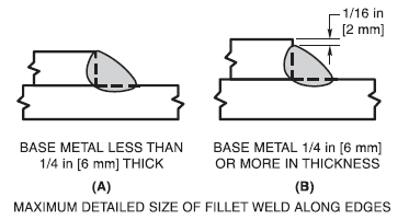
Answer: The thickness of the upper member minus 1/16 inch [2mm] as shown below.
Explanation: This is a relatively simple question and one whose answer is easy to remember and/or easy to find. The above diagram is from Figure 2.1 of AWS D1.1/D1.1M:2015. What is not easily understood is why, unless the base metal thickness is 3/16 [5mm] or less, we cannot make the weld flush with the upper member as shown in image (A) above. The need for the 1/16 inch [2mm] dimension is simply for inspection purposes. When you weld this flush it makes it extremely difficult to measure the weld because the edge of the upper plate is gone and we have no point of reference.

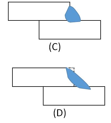
The image above shows how the perceived weld size can be misleading in terms of knowing the true load bearing capacity of the weld.
As you can see in the image above, from the exterior of this weld it would appear that weld “D” is much larger than weld “C” when the opposite is true. In this example weld “D” didn’t even reach the root of the joint. Weld “C” is bigger because it has a bigger effective throat.
IMPORTANT NOTE: In some cases were the rule of leaving a 1/16 inch [mm] dimension at the top of weld is violated, some CWIs will make a fabricator fix the issue. As you can imagine the only way to fix it is to remove the weld and in some cases scrap a lot of the base metal. If this ever happens what is needed is for the Engineer in charge to OK the weld. There are very few instances were violating this requirements will affect structural integrity. However, it is not the CWIs job to make this call; it is the responsibility of the Engineer.
Additionally, the shop drawing (by design or other reasons) may call for the weld to be flush with the upper member. Thus not requiring to conform to the mandate found in Clause 2 to maintain that 1/16 inch [2mm] dimension.
The answer to this questions can be found in Clause 2.4.2.9 and Figure 2.1 of AWS D1.1/D1.1M:2015.
- What is the maximum amount of reinforcement for a complete joint penetration (CJP) groove weld on base metal having a thickness of 3/8 inches [10mm]?
Answer: 1/8 inch [3mm]
Explanation: First of all, the term reinforcement is misleading since reinforcement in a weld does not provide much, if any reinforcement (additional strength). The reason why there is a maximum allowed height is because the higher the reinforcement the more abrupt of a transition we would have at the toes of the weld. This becomes a stress riser which can cause the weldment to fail prematurely, especially in service conditions subject to fatigue loading.
Unlike the issue in question 1, this is one that must always be corrected. A mistake that is often made is to simply grind off the top of the weld and leave the toes untouched. Remember, it is the geometry at the toes, the lack of a smooth transition, that creates the stress concentration. To repair this properly the reinforcement must be trimmed but the toes must also be treated to eliminate the abrupt angle formed between the surface of the base metal and the face of the weld.
This answer can be found in Tables 5.8 and 5.9 as well as Figure 5.4 of AWS D1.1/D1.1M:2015.
- For applications requiring Charpy V-notch (CVN) testing, by how much would preheat and/or interpass temperature need to go up to necessitate the requalification of the WPS?
Answer: By 100˚F [56˚C]
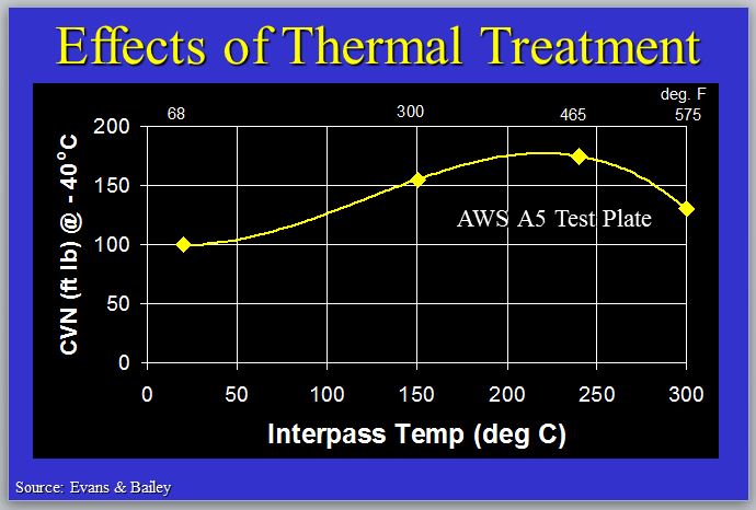
Explanation: CVN tests for toughness, or the weld metal’s (or base metal’s) ability to absorb energy and resist the propagation of a crack. This is especially important in very low service temperatures. The reason why requalification is needed when the preheat and/or interpass temperature exceed that shown in the procedure qualification record (PQR) by 100˚F [56˚C] is because the higher the preheat/interpass temperature the slower the weld and adjacent heat affected zone (HAZ) will cool. The slower the cooling the rate the larger the size of grains. And the larger the grain size the lower toughness the weldment will exhibit.

Heat input, preheat temperature and interpass temperature all have an effect on weld metal and HAZ toughness
It is important to note that too low of a preheat or interpass temperature can also have a detrimental effect on toughness. However, this is not addressed in requalification requirements simply because we should never be below the interpass and preheat temperature stated in the WPS.
This answer can be found in Table 4.6 of AWS D1.1/D1.1M:2015 under “Electrical Characteristics.”
- What do the numerical figures on the welding symbol below indicate?
Answer:
- 1/8 inch root opening
- 45˚ included angle
- ¾ inch depth of groove preparation
- 7/8 inch weld size (meaning the weld must penetrate an additional 1/8 inch beyond the depth of groove preparation
Explanation: CWIs, welders, supervisors, quality personnel, welding engineers and many others must know welding symbols. For a CWI the welding symbol above provide the information necessary to inspect a joint before welding. The root opening, the bevel angle and depth of bevel prep can all be verified against the symbol. For a welder the symbol is important to understand that a certain amount of penetration beyond the root is required.
In many cases, knowing how to read welding symbols will allow a welder to easily know the number, length, size, location, bead contour and other requirements of a weld or set of welds.
Can you interpret and write welding symbols? Test your knowledge by taking our FREE Welding Symbols Practice Test.
The answer to this question is found in AWS A2.4 – Standard Symbols for Welding, Brazing, and Nondestructive Examination.
- What is the maximum size of a crack allowed by AWS D1.1 when performing visual inspection (VT) for cyclically loaded nontubular connections?
Answer: Zero. Any crack shall be unacceptable, regardless of size or location.
Explanation: This should require no explanation. A crack has very sharp ends and can propagate easily. It is one of the worst, if not the worst weld discontinuity. Cracks can lead to premature failure.
The question is specific to cyclically loaded nontubular connections. However, the answer is the same for tubular cyclically loaded connections as well as statically loaded tubular and nontubular connections.
References:
Qualification of Welding Procedures, Welders and Welding Operators
Welding Symbols Training Manual
AWS D1.1/D1.1M:2015 Structural Welding Code – Steel
AWS A2.4 – Standard Symbols for Welding, Brazing, and Nondestructive Examination


Simple, but very useful explanation.
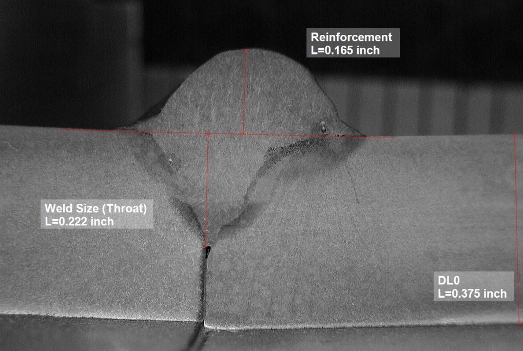
At point number 2, the picture shows a weld size (throat) of 0.222 inch.
There is a straight dark black line on the left side piece that could be interpreted as a lack of fusion and thus, reduce the weld size (throat). Can you give us the explanation why it’s not the case ?
Thanks, your work are very appreciated,
Mark
Hello Mark. Thanks for your comments and excellent observation! The dark spot you are referring to is barely inside the weld zone so it’s probably not lack of fusion, but porosity. I have the sample back at the lab so I will take a closer look and verify this. The discontinuity is not linear or sharp but appears to have round edges. When I prepared the sample by grinding and polishing it could have caused the round edges to be blurred on the image. But you are absolutely correct, if it is in fact lack of fusion it would reduce the effective throat of the weld. And it can certainly be interpreted as lack of fusion by just going off of the picture.