Cracks on welds are never good. Welding codes always have allowances for porosity, undercut, weld sizes, and even weld profiles. However, there is never an allowance for cracks. Being a linear discontinuity, a crack will tend to propagate through the weld and into the base metal with relative ease, especially in cyclically loaded structures. So naturally we want to avoid cracks at all costs.
Below is a list of 6 mistakes you need to avoid in order to reduce cracking susceptibility.
- Using a matching filler metal – there is a misconception that because codes list matching filler metals (to base metals) that we must use these. In the vast majority of cases using matching filler metals presents absolutely no problems. In the case of complete joint penetration welds (CJPs) it is necessary. But in some cases, matching the strength of the base metal with the filler metal may lead to cracking.
When we are dealing with high strength steels the use of undermatching filler metals may be advantageous. Why? Because the lower strength will provide a more ductile weld compared to using a matching filler metal. Lower residual stresses are also a benefit of using undermatching filler metals. If you are making partial joint penetration welds (PJPs) or fillet welds on high strength steels consider using undermatching filler metals when permitted. You can always add strength to the connection by making the weld bigger, but ductility will remain the same.
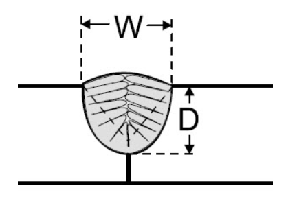
- Excessive width-to-depth ratio – welds should have a width-to-depth ratio of about one to one. A weld nugget will go from molten metal to solidified metal in the same way that water turns into ice in a glass left in the freezer. Solidification begins from the outer edges and progresses towards the middle. If steels have a significant amount of tramp elements, specifically those with low melting temperatures like copper, you run the risk of solidification cracking. These low melting temperature elements are driven to the middle of the weld and solidify last. Leaving crack-like discontinuities that can easily reach the surface of the weld.

Solidification of the weld nugget starts on the outer edges as heat is dissipated away from the weld. Any low melting temperature elements wills segregate towards the middle of a weld and solidify last.
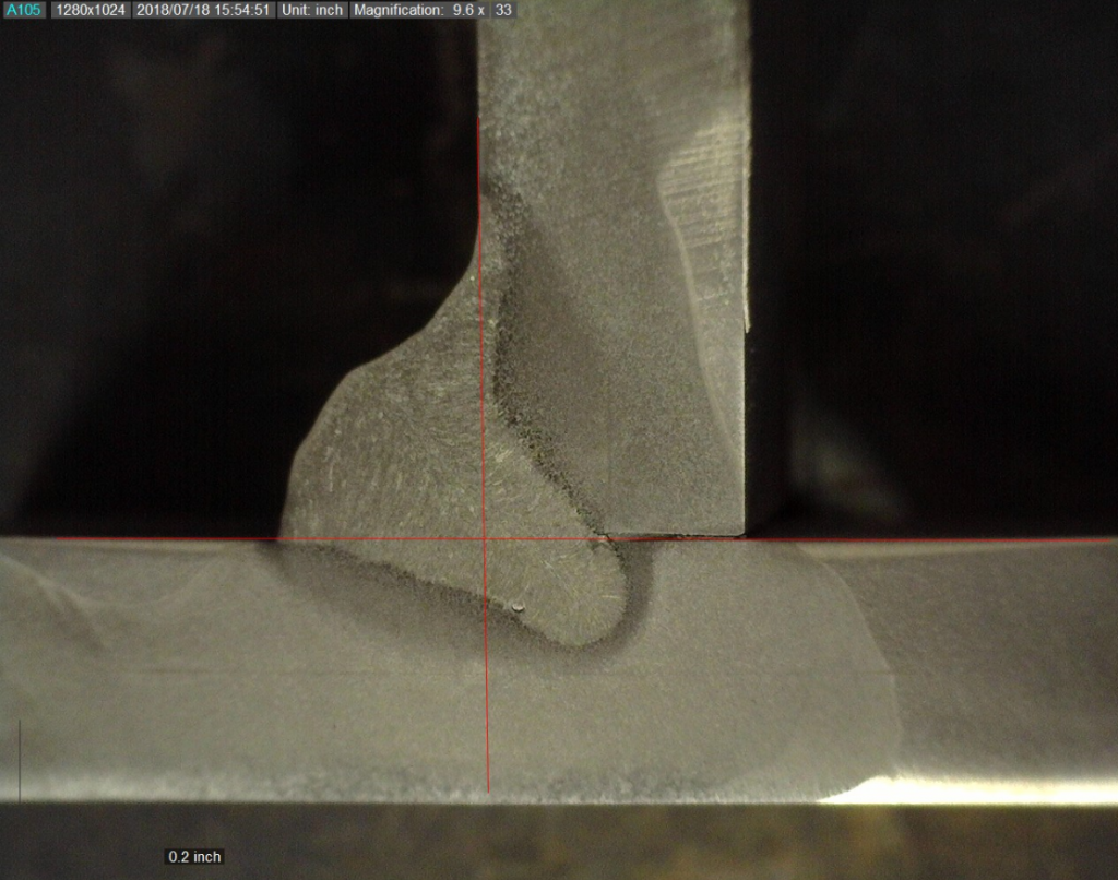
When you have a weld that is significantly deeper than it is wide this problem is exacerbated. The weld shown below has tremendous amount of penetration which we normally consider a good thing. As you can see the penetration profile is very deep and narrow. There was no cracking in this case; however, if the base material had elevated levels of impurities this weld would be susceptible to solidification cracking.

Deep penetrating welds are susceptible to solidification cracks. The base material chemistry plays a huge role in this as impurities will increase the probability of a crack.
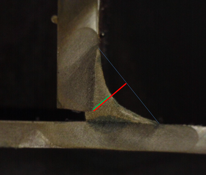
- Surface profile – extreme concavity. If you have two welds with exactly the same leg size but one is flat and the other is concave, the concave weld will have a much smaller effective throat. The load carrying capacity of a weld is proportional to its effective throat size. Some welds, especially vertical down welds like the one seen below can have almost no throat and when subjected to heavy loads may crack.

The red line represents the desired dimension of the weld throat. The weld’s concavity creates a reduction in the throat dimension represented b y the green line. There is a reduction of about 50% in the load carrying capacity of this weld due to its extreme concavity.
- Ignoring low-hydrogen practice when required – if you read our articles often you know we constantly talk about hydrogen induced cracking. There are three things that need to be present for hydrogen induced cracking to occur: First, a susceptible microstructure. Second, a highly restrained connection. And third, a source of hydrogen. We hardly ever have control over the first two, but we can certainly control the third. Do not make mistakes that will lead to hydrogen induced cracking. Using low-hydrogen practice will help you prevent hydrogen induced cracking.
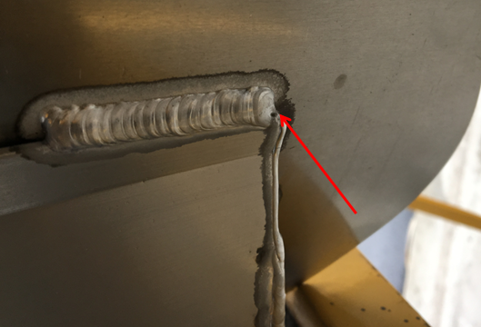
- Not filling craters – weld terminations where the full cross section of the weld is not achieved can be problematic and lead to cracking, especially when welding aluminum. Craters reduce the cross sectional area of the weld and create stress risers. They also create solidification cracks which greatly diminish the fatigue life of the weldment.
In aluminum, this problem can easily be solved by using a back stepping technique or utilizing crater fill options in advanced power sources.
- Using the wrong shielding gas mixture with FCAW wires – mixes of argon and carbon dioxide are the typically used when welding with the flux-cored arc welding (FCAW) process. FCAW wires are tubular and are filled with flux. The flux contains alloying elements which contribute to the weld’s mechanical properties. Since argon is an inert gas it does not create any chemical reactions that lead to a loss of these alloying elements. Carbon dioxide on the other hand is an active gas and its chemical reactivity leads to loss of some the alloying elements in the flux. So the higher the carbon dioxide content the higher the loss of alloying elements. This results in a loss of strength (tensile strength). But before you think that increasing our carbon dioxide content is the problem let’s look at what happens when you increase the argon content.
When we increase the argon content we retain more of the alloying elements added to the FCAW wire. This in turn increases our tensile strength. With increase in tensile strength comes increase in hardness and a decrease in ductility. A loss of ductility can then lead to cracking. Always follow the filler metal manufacturer’s recommendations for gas mix for a particular electrode. Do not exceed the maximum allowable percentage of argon under no circumstances.
Reference: Welding Procedure Development for Non-Welding Engineers


It has been quite some time that I have been unclarified about using undermatching filler metal or electrode are used until I found this blog. THANKS TO THIS BLOG, I am clear now and overwhelmed with joy as if I discover the answer for a puzzle.
However sorry to say that, I don’t understand why I cannot purchase online from the country where I live for QUALIFICATION OF WELDING PROCEDURES, WELDERS AND WELDING OPERATORS By Welding Answers.
Thank you for you comment. I will contact you via email regarding the Qualification of Welding Procedures eBook.