
The ability to interpret welding symbols is very important, yet the vast majority of welders have hard time doing so. A very small percentage of companies require that welder candidates know how to read symbols. With the shortage of welders in today’s market imposing this prerequisite would not be feasible.
What companies need to do is to have training for their welders. The problem is that in many cases fabricators don’t have someone on staff that can do this. This is usually the case in small to medium size companies. However, if you are in need of this kind of training you can rely on outside help. Vendors, mainly industrial distributors and welding equipment manufacturer’s representatives, should have this knowledge. At least highly qualified ones do. They typically can offer this type of training at no cost or at a low fee.
The 9 steps below represent a very basic introduction to welding symbols. This is just barely skimming the surface of weld symbols training. If you have a questions please let us know by replying to the post.
Welding Symbols Basics
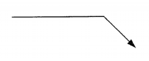
- Every weld symbol must consist of an arrow and a reference line.
- The arrow may point up or down
- The arrow does not necessarily need to point to the side of the joint that needs to be welded. Sometimes space constraints in the drawing will not allow for the arrow to fit on one side, so the information placed on the reference line will be an indication of whether the weld goes on the arrow side or the opposite side.
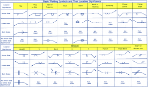
- The type of weld joint is indicated by a specific symbol. The American Welding Society has a very nice chart detailing these symbols. Below is a section of it.
Going forward we will stay with Fillet welds since the following information is displayed differently depending on the type of weld joint.
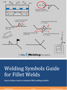
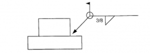
- Information such as size, length and other special considerations will be displayed next to the weld symbol. Location of this information matters. Below we see an example of a fillet weld symbol.
Fillet weld symbols will ALWAYS have the vertical line of the symbol on the left.
- The length of the fillet weld, if it is not the entire length of the join, is displayed to right side of the symbol.
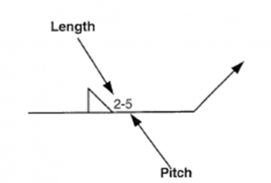
- Intermittent welds are called out using Length and Pitch. As noted above the number to the right of the diagonal line of the fillet symbol is the length (in the US this will be in inches unless otherwise noted). The pitch is displayed to the right of the length and it indicates the distance between centers.
- VERY IMPORTANT: if you ever see a flag at the intersection of the reference line and the arrow do NOT make that weld if you are in a shop. This flag indicates this weld must be done in the field.
The circle notation means the weld has to go all the way around.
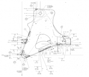
- Several of the diagrams above show the configuration of the base material (graphical representation of the joint by showing how the two pieces come together). This is almost never the case on an actual drawing, and thus it is why it is important to know the different welds symbols shown on the AWS Symbols Chart. A drawing will more than likely look something like this:
This was a very basic introduction to weld symbols. Training programs that we have gone thru or put on for customers range between 4 and 16 hours. Programs are typically tailored to the customer’s need and thus vary widely in length.
Want to learn about welding symbols for groove welds? Check out 9 Basic Steps to Reading Welding Symbols for Groove Welds.
Source: Welding Symbols Training Manual





YES
I was taught Trigonometry and blue print reading @ local 60, plumbers and pipe fitters union along with welding skills.
I appreciate the information you guys post.
Education is Key.
Thank you, Rick
Thanks for your comment Rick. We appreciate it!
Please let me know how to calculate the practical throat of a bevel well and over that a fillet weld. This refers to a T joint, the leg of T having a bevel of 45 degrees.
For a fillet weld reinforcing a groove weld you DO NOT add the throat off each. Rather, you measure the shortest distance from the joint root to the weld face of the diagrammatic weld. I will send you some sketches to your email address so you can see this graphically. Or, if you have a copy of AWS D1.1 you can look at Annex A (Figure A.3 if you have the 2015 edition
I went to welding school and didn’t unfortunately get taught much about this, can you send me information that I could teach myself?
****Also sometimes I get confused when looking at a blueprint/drawing in ISO mode. I mean I get the whole front view, top view, and side view, but sometimes when looking at it I get confused. Can you recommend a trick to the trade or am easier way to get it? I’m just starting a jobe getting my experience in the field at a shop. Maybe I’m a little nervous or over worried but I guess we’ll see. Passed the welding test though.
Thanks
Hello Chris, you are correct in how to calculate the effective throat of a groove weld with a reinforcing fillet weld. You do not add the dimension of the throat of both welds, rather, you go from the deepest point of root penetration to the face of the reinforcing fillet weld.
Thank you for the helpful information
The weld symbols in part 9 are incorrect, you are confusing the other side of the part with the other side of the joint.
Thanks for note Terry. You are right. We were trying to show what a typical drawing looks like but should have made sure there were no inconsistencies. We will replace this drawing with one that has not mistakes. Thank you.
Please let me know how to calculate the practical throat of a bevel well and over that a fillet weld. This refers to a T joint, the leg of T having a bevel of 45 degrees.
For a fillet weld reinforcing a groove weld you DO NOT add the throat off each. Rather, you measure the shortest distance from the joint root to the weld face of the diagrammatic weld. I will send you some sketches to your email address so you can see this graphically. Or, if you have a copy of AWS D1.1 you can look at Annex A (Figure A.3 if you have the 2015 edition).
I took a blueprint assessment test for this company i applied for. I didn’t pass it, but will be given another chance, could you please help me on where i could see a blueprint and would ask me questions related to that blueprint. Thanks
Do you need help with general blueprint reading or with welding symbols? Please send us an email through the “Contact Us” link on our site. Please provide as much detail as you can. We’ll be happy to help however we can.
hi thanks i have quastion which would you like to choose as electrod for low alloy steel for useing pressure vessel materiyal selection?? where is the selection guide in asme???iwill de happy if answer to me
What is the base material you are welding? You can reference the ASME Boiler & Pressure Vessel Code.
As me 2c can use to select electrod material
Cant wait for my free welding book.
I am looking for a laminated wall chart of welding symbols, size 3′ x 4′ if available.
If not this size let me know what size is available.
This is not that size, but may be a helpful pocket guide.
http://www.amazon.com/gp/product/1889892742?ie=UTF8&camp=1789&creativeASIN=1889892742&linkCode=xm2&tag=weldianswe06-20
You can also download a free PDF copy and then blow it up. http://www.AWS.org should have it readily available.