
There are four types of loading experienced by welds and welded structures. These types of loading are a function of the strain rate (the rate at which deformation occurs in a material due to an applied load) and the number of loading cycles experienced by the welded member.
The 4 types of loading are:
- Static Loading
- Fatigue Loading
- Shock Loading
- Shock/Fatigue Combination Loading
Static Loading
Static loading occurs when a force is applied to a welded member at a slow and/or constant rate. For the design engineer, static loading may be the easiest to design for. That is because the loading is constant, there is no change over time. Examples of welded structures subject to static loading include buildings, dams, mezzanines and some tanks.
Fatigue Loading
Fatigue loading occurs when a welded structure experiences an alternating, repeating or fluctuating stress. Fatigue loading is divided into low cycle fatigue and high cycle fatigue. Low cycle fatigue is characterized by high stress levels typically above the yield point and failure in less than 1000 cycles. High cycle fatigue is characterized by low stress levels below the yield point and failure after more than 10,000. Examples of welded structures are bridges (varying loads due to passing vehicles and wind), metal stamping presses, cranes and rotating shafts under bending loads.
Shock Loading
Shock loading is experienced by a welded member when an impact-type force is applied rapidly. Cranes are an example of fatigue loading because they are constantly picking up and releasing heavy loads. However, they can also be an example of shock loading. This occurs when loads are lifted before slings are tight. This creates a shock loading condition. Another example of shock loading is an armored vehicle being impacted by a missile or other type of explosive.
Shock/Fatigue Combination Loading
Shock/Fatigue combination loading, as the name implies, is a combination of fatigue and shock loading. Examples of this combination loading include pile drivers, jack hammers and ore crushers.
Design engineers as well as fabrication personnel (welding engineers, welders, fitters, inspectors, etc.) must understand these 4 types of loading conditions in order to design and fabricator welded structures and members that hold up to the expected service demands. Weldments that hold up well under static loading may fail in fatigue loading due to design errors, such as specifying a prohibited joint in cyclic applications. Or it may fail due to welding discontinuities such as undercut that may not pose much of a threat in static loading but could easily initiate a crack under cyclic loading.
Estimating the fatigue life of a welded connection considers many variables. Both AISC and AWS provide guidance, but the design engineer must have a sound understanding of not just the type of loading but also the magnitude and the frequency.
Inspectors and other quality personnel must understand these types of loading because they may change the acceptance criteria. We need to look no further than AWS D1.1 Structural Welding Code (Steel) for this. In Clause 8 (Inspection) of the latest edition of AWS D1.1 (2020), Table 8.1 provides acceptance criteria which differs for statically and cyclically loaded connections.
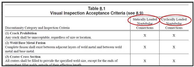
Table 8.1 from AWS D1.1 (2020) provides the inspection criteria for many welding discontinuities. The snippet above shows the first three, all of which are treated the same regardless of whether the welded structure is statically or cyclically loaded. However, once you get down further on this table there are differences in the allowances for discontinuities such as undercut and porosity.
In the case of shock loading, designers must understand that the strain rate will be much higher in such situations; however, the elongation of the material remains the same. This is because shock loading has an acceleration component that magnifies the load. Designers must be aware of this and design accordingly.
Most engineers are used to the principles of static loading and struggle in the presence of fatigue and shock loading. This is one of the reasons why there are many inefficiencies in design. If a design engineer does not understand the loading types well they will end up designing for the worst case scenario. This leads to unnecessary complete joint penetration (CJP) welds being called out when partial joint penetration (PJP) welds would suffice.
What type loading are the parts welded in your facility subject to? Does your quality standard distinguish between static and cyclically loaded members?
References:
AWS D1.1/D1.1M:2020 Structural Welding Code – Steel
What the Design Engineer Should Know About Welding, Omer W. Blodgett