

The design of pressure vessels is quite interesting. At first it may appear extremely complicated. Then, you learn the basics of pressure vessel design and realize it is not that big of a deal. But, then you get into all variations of vessel heads and shells, the different kinds of loading conditions (it’s not just internal pressure), and the economics of design and you go back to thinking it is too complex.
The truth is that the design of pressure vessels does not have to be complicated. We have the benefit of having had many bright minds develop formulas for the design of pressure vessels. We basically just need to plug in the values and we’re set. Well, it’s not that easy.
The designer of pressure vessels must be well versed in three areas:
- The latest version of the applicable code (i.e. ASME BPVC, Section VIII, Div 1)
- Techniques used in design to meet the applicable code
- Selection of material properties and dimensional data from various handbooks
It is common to assume that pressure vessels only deal with internal pressure, as in the case of a boiler. However, vessels are also designed to sustain external pressure, as in the case of a submarine. Furthermore, in some cases we need to consider wind loading, seismic loading, vibration, eccentric loading, elastic stability, deflection, combination of stresses and so forth. Now you can see how pressure vessel design can become troublesome for the novice designer.
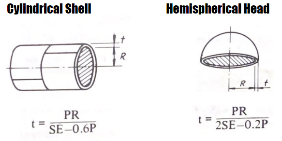
To illustrate the basics of pressure vessel design we will go through an example for the selection of plate thickness for a cylindrical pressure vessel with hemispherical heads.
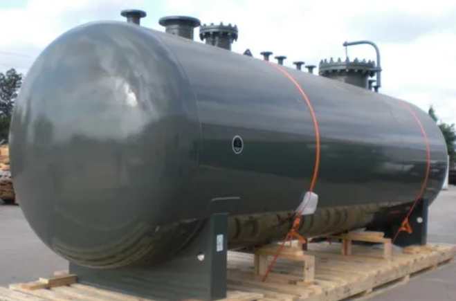
As seen in the image above, pressure vessels have many openings with several welded attachments. For our example we will disregard those for simplicity.
Example: You are a design engineer in charge of determining the wall thickness for the shell and the head of a pressure vessel. The base metal has been selected and it is SA 515 – 70 plate for both the shell and the head. The following data is also available:
P = 100 PSI, design pressure
S = 17,500 PSI, stress value of SA 515 – 70 plate @ 650°F [345°C]
E = Efficiency of spot-examined joints of shell and hemispherical head to shell
R = 48 inches inside radius (always add 0.125 for corroded conditions)
D = 96 inches inside diameter
t = Required wall thickness (this is what we are solving for)
C.A. = 0.125 inches, corrosion allowance (this number is added to “t”)
It is important to note that uniform internal or external pressure induce a unit stress two times larger in the longitudinal seam than the circumferential seam because of the geometry of the cylinder.
Back to our example.
Shell Thickness
To determine the thickness of the shell we plug in the values on the cylindrical shell formula.
t = (100 x 48.125) / (17,500 x 0.85 – 0.6 x 100) = 0.325 inches
Remember, we need to add 0.125 for corrosion allowance (C.A.) so the thickness of the shell is
t + C.A. = 0.325 + 0.125 = 0.450 inches
Use 0.500 in (½ inch plate)
Head Thickness
Now let’s calculate the thickness necessary for the head using the hemispherical head formula
t = (100 x 48.125) / (2 x 17,500 x 0.85 – 0.2 x 100) = 0.162 inches
t + C.A. = 0.162 + 0.125 = 0.287 inches
Use 0.315 inches
Simple enough, right? Just make sure you use the right formulas. If instead of a hemispherical head we had an ellipsoidal head the thickness would be different. Using the formula for a 2:1 ellipsoidal head the resulting necessary thickness would be 0.4375 inches.
And if that wasn’t enough variation for you, there are conical heads, dished heads, circular flat heads as well as some other interesting geometries.
In this example we were only concerned with internal pressure. We may need to design for external pressure and consider all those other loading conditions we mentioned above.
One more thing to note. A design engineer will use these calculations to determine the thickness of plate that needs to be used. But he or she will also consider other materials. Steels with higher strength would not need to be as thick. This can reduce weight. However, it can significantly increase cost. But that’s just the cost of the plate. The amount of welding necessary will be much less if the thickness of the plate is less. So it becomes a balancing act. Many times, using stronger, more expensive plates results in a lower cost of manufacturing. As you can see, design goes beyond simply following design formulas. A designer must always consider cost.
REFERENCE: Pressure Vessel Handbook, 14th Edition