Have you ever noticed that there are design rules that prohibit sizing a fillet weld below a certain size for a given thickness of material? If you look at AWS D1.1/D1.1M:2020 Structural Welding Code (Steel) you can find this on Table 7.7. If you happen to own a copy of AISC 360-16 Specification for Structural Steel Buildings you’ll find this on Table J2.4. Or if you have the always helpful Procedure Handbook for Arc Welding you can find it on Table 2.7. Even better, go to Omer Blodgett’s Design of Weldments and you’ll find the same data on Table 1 of Section 6.3.
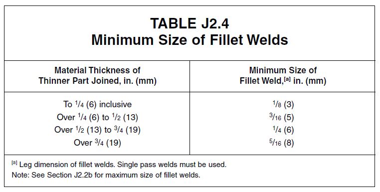
Below you can see AISC’s Table J2.4 – Minimum Size of Fillet Welds.
If you are thinking that the minimum fillet weld sizes are specified in order to avoid making welds that are too small and consequently not strong enough, you are the majority and are in good company. But you’re also wrong. Most fillet welds are not required to be full-strength. Most are used when the welded member is designed to maintain a certain amount of stiffness or rigidity. In these cases the stresses are quite low and if calculated properly would require welds that are smaller than 1/8”.
There are a couple of problems with making a 1/8” weld (or smaller). First, it is not easy to make that small of weld and get adequate fusion. And second, the heat input would be so low you risk embrittlement due to rapid cooling which can cause hydrogen induced cracking (cold cracking).
This second problem is the reason for having minimum weld sizes. We typically don’t think about hydrogen induced cracking on low carbon steels, especially not on thin sections (1/4” or less). If we don’t need to preheat and maintain a certain interpass temperature we may incorrectly assume that we are not at risk of cold cracking. This however is not true. Making a very small weld with extremely low heat input can still create a martensitic microstructure on thin sections of low carbon steels.
If you look at the footnotes on the table above you’ll see that they specifically call for the minimum weld sizes to be made in a single pass. If the minimum fillet weld size is ¼” you cannot make two welds to achieve that size. Remember, we are concerned about heat input, not the final size of the weld.
The premise behind this is that the required minimum weld size will provide a sufficiently high heat input into the plate to provide the desired slow rate of cooling.
What about welding dissimilar thicknesses?
Furthermore, although not noted on Table J2.4 there is one more consideration. If we are welding plates of dissimilar thickness we would consider the thickness of the thinnest plate when determining the minimum fillet weld size. This is true only if we are using a low-hydrogen process. If not, then we use the thicker plate to determine the minimum weld size.
Most of us have never had to worry about these issues. Why? Because we all participate in the overwelding epidemic that is costing our industry billions of dollars every year. We continually urge our consulting customers to take a look at their designs and evaluate the use of minimum fillet weld sizes. This is not always a viable alternative, but it is certainly worth looking into.
If you don’t think overwelding can cost you dearly, we suggest you read The Outrageous Cost of Overwelding. Take a look, you will be surprised.

References:
The Procedure Handbook for Arc Welding – 14th Edition
AWS D1.1/D1.1M:2020 Structural Welding Code – Steel
AISC 360-16 Specification for Structural Steel Buildings
Design of Weldments – The James F. Lincoln Arc Welding Foundation
Need help troubleshooting weld and welding equipment related problems?
For more information CLICK HERE or the image below.
- Learn and follow the process used by welding engineers to find the root cause of welding problems and their solutions.
- This troubleshooting guide goes beyond your typical troubleshooting charts on the back of an owner’s manual. The goal is not just to help you solve a welding problem, but to teach the concepts and theory behind it. Understanding why a recommended solution worked is just as important as solving the problem.
- This guide addresses the most common weld discontinuities as well as the most common welding equipment problems.
- Use this publication as a training tool for welders, supervisors, inspectors, quality personnel and even seasoned welding engineers.