
The following is an exerpt from: TROUBLESHOOTING FOR NON-WELDING ENGINEERS
There is nothing wrong with concave welds so long as they attain the desired throat dimension. AWS D1.1/D1.1M:2020 Structural Welding Code (Steel) states that “there is no restriction on concavity as long as minimum weld size (considering both leg and throat) is achieved.” Concave welds with adequate throats are not a problem.
Concave welds are actually good for transferring stresses since they have very smooth transitions at the toes. They are excellent in fatigue loading conditions. The problem comes when the throat dimension is not adequate. If the design calls for a 1/4–inch fillet weld leg size, the assumption is that the weld has a flat face and has a minimum throat dimension of 0.177 inches. If the leg size is achieved, but the weld is concave, the throat will be less than 0.177 inches and thus undersized. This can lead to centerline cracking.

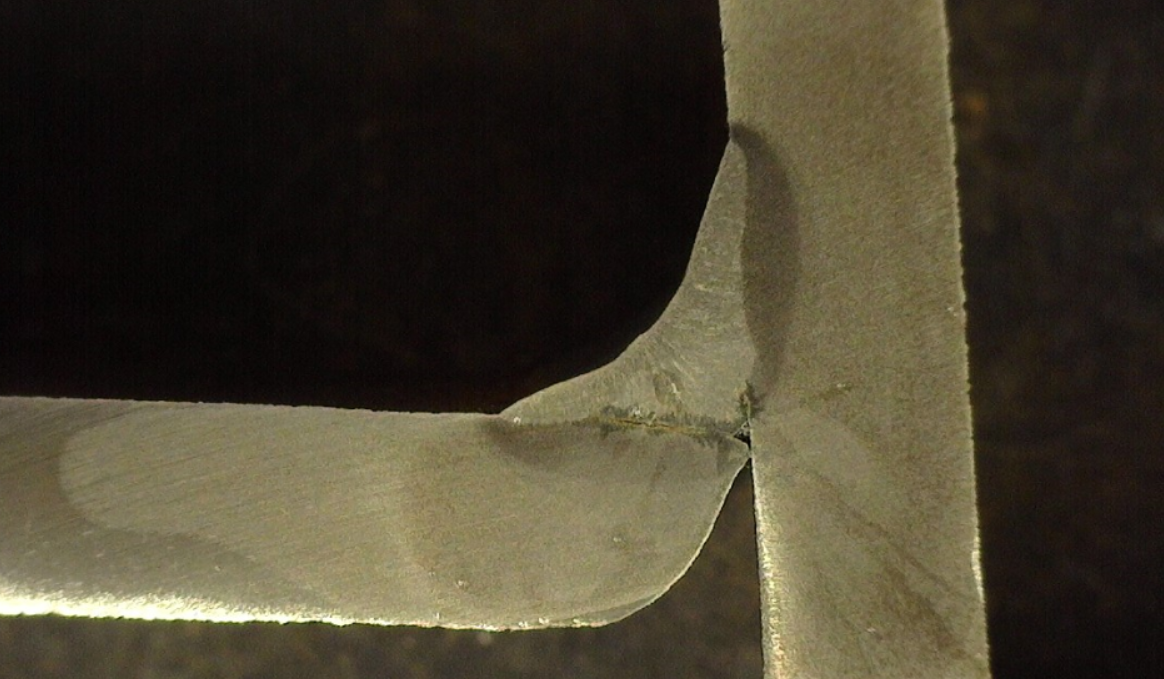
Concave welds are also prone to other discontinuities such as incomplete fusion. This is due to the fast travel speeds typically associated with concave welds. The fast travel speed drastically reduces heat input and fusion may be compromised. The figure above shows incomplete fusion on the bottom leg of the weld.
So what causes concavity and how can we correct it?
Probable causes and fixes for CONCAVITY.
Cause: Travel speed is too fast
When the welding travel speed is too fast, weld metal cannot be deposited fast enough to avoid concavity. There just isn’t enough weld metal to create a flat weld face. Welding procedures should always specify a travel speed range. Travel speed is an essential variable that must be specified in all welding procedures to ensure sound welds. Going below, or exceeding this travel speed range can generate undesirable conditions.
Solution 1: Reduce travel speed
Reducing travel speed will allow for sufficient weld metal to be deposited to produce a flat to slightly convex weld face.
Solution 2: Avoid welding vertical down
Welding in the vertical position with downward progression (vertical down) is conducive to extremely fast travel speeds. Welders speed up in order to prevent the molten weld puddle from rolling ahead of the arc and causing problems like incomplete fusion, spatter and overlap. This is due to gravity forcing the weld metal down at a fast rate. If at all possible, position the part so that it can be welded in the flat or horizontal position.
Cause: Voltage is set too high
As voltage goes up, arc length increases. Long arc lengths spread the weld out and smooth out the toes, but also can create concave welds as shown in Figure 4.1-2.
Solution 1: Reduce voltage
Reducing voltage will reduce the severity of the concavity.
Solution 2: Increase amperage/deposition rate
Increasing amperage increases deposition rate. Higher deposition rates mean more fill. By doing this you are increasing the amount of weld metal deposited per unit time (lb/hr) and provide more fill to avoid concavity.
REFERENCE:
Troubleshooting for Non-Welding Engineers
- Learn and follow the process used by welding engineers to find the root cause of welding problems and their solutions.
- This troubleshooting guide goes beyond your typical troubleshooting charts on the back of an owner’s manual. The goal is not just to help you solve a welding problem, but to teach the concepts and theory behind it. Understanding why a recommended solution worked is just as important as solving the problem.
- This guide addresses the most common weld discontinuities as well as the most common welding equipment problems.
- Use this publication as a training tool for welders, supervisors, inspectors, quality personnel and even seasoned welding engineers.
- Can help Welding Engineers as well. Most welding engineers are in charge of specific product lines, or work for a single company and are limited in terms of their experience troubleshooting welidng problems. They can be experts in a specific welding process and fixing issues related to the type and thickness of materials they deal with on a daily basis. But when a new application comes along that uses a different welding process or a type of material that is quite different and then it becomes harder to troubleshoot.