When a weld fails we don’t always know what caused it. We may try something different and if it doesn’t fail the next time we adopt that as the new standard. However, it is very important to know the root cause of weld failures. If we don’t know what caused the failure how can we be sure it won’t happen again? Or how can we know that the changes are not making things worse?
The following case is a real life example of how ignoring the need to determine the root cause can lead to additional and more costly failures.
A manufacturer was welding a solid shaft to a disc. This subassembly later became part of rotating equipment which supported a lot of weight. The solid shaft was made from AISI 1045 steel and was 1.5” in diameter. The disc was made from ASTM A572 Grade 50 steel and was ½” thick. This was welded with 1/16” ER70S-6 mig wire and C10 shielding gas (90% Argon, 10% Carbon Dioxide). The process did not call for preheat. One day they received a call from their customer saying the shaft had broken. This was a big problem that affected their customer creating downtime and significant losses.

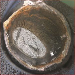
Image of the fractured surface of the shaft. The failure was in the HAZ. The surface also indicates that this failure occurred over time due to cyclic loading. The crack propagated slowly over time until it reached a critical length and then the part experienced complete failure.
Instead of investigating the root cause the manufacturer decided that a good course of action was to use a higher tensile strength wire. They switched to ER90S-D2 wire. They did not have any issues in the next few months. However, they eventually had another failure, and then another. It was the exact same type of failure. Using a higher strength filler metal didn’t help. As a matter of fact, it made things worse. This was an action that showed the manufacturer did not have an understanding of how to weld medium and high carbon steels.
This time the manufacturer took things more seriously and decided to investigate the cause of these failures. We were called in to help. It didn’t take fancy equipment such as scanning electron microscopes to evaluate the failed samples or an expert understanding of fracture modes to determine the cause. It simply took an understanding of the base materials being used, the welding process and the welding codes that govern this type of application.
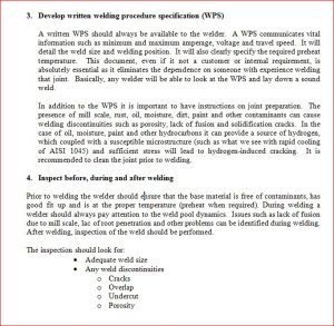
Our report included over 15 recommendations to avoid the problem in the future. One of the most important recommendations was to develop and qualify a welding procedure for that specific weldment. Another recommendation was to send inspection personnel out to the field and evaluate all of the welds made in the past 28 months. Why? Because until the day we implemented the new welding procedure the way they were welding this shaft created a high probability of cold cracking due to embrittlement of the heat affected zone. As you can imagine this represented a huge expense for the manufacturer, but it had to be done. Seven repairs were made in the field which potentially saved our customer thousands of dollars by preventing more failures. However, all of this would have been avoided if the manufacturer had a quality control procedure in place which required the use of qualified welding procedures.

Screenshot of the recommendations sections for avoiding this failure in the future. Development and qualification of proper welding procedures is essential.
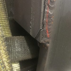
Some may have already figured out what the problem was, but in case you are still wondering this is what happened. AISI 1045 is a high carbon steel and must be preheated to prevent embrittlement of the heat affected zone from welding. The application of preheat slows the cooling rate and reduces or avoids the formation of martensite in the HAZ. Preheat was never part of their process. The welding procedure being used (with 1/16” ER70S-6) was actually a relatively high heat input process which partly compensated for the lack of preheat. At times, the welders would switch to .045” ER70S-6 wire when the 1/16” was out of stock. The heat input with the .045” wire was much lower. This caused a faster cooling rate and embrittlement of the HAZ. Still, this by itself was not enough to create the failure. Upon examining the failed samples it was discovered that all which had failed had undercut where there the crack initiated. The toe of a fillet weld is always a high stress point. Add a brittle HAZ and an additional stress riser (undercut) and you have a recipe for disaster.
As mentioned before you do not need fancy lab equipment or a metallurgy degree to perform basic forensic engineering. Anyone can follow basic steps to determine root cause or at the very least help those that you hire to do this for you. If you been following us for a while you may know we use and recommend the book “Welding Metallurgy and Weldabilty” by John C. Lippold. In this book, Lippold devotes an entire chapter to failure analysis. This chapter goes in depth into the different types of testing needed to determine fracture modes. Great information for the welding engineers out there. However, these principles can easily be followed by anyone. The following list are basic steps taken out of the above mentioned book that can help you get started.
Weld Failure Analysis Basic Steps
- Visit the site
- Collect all available data
- Welding Procedure Specifications
- Base metal material test reports
- Pictures of the failed part (you can never have too many pictures). If you cannot be on site before the part is repaired make sure someone takes pictures for you.
- Samples of the failed part for further analysis if available and necessary.
- Service conditions (weather, application specifics, type of loading, etc.)
- Interview personnel – this is very important especially in the absence of welding procedures specifications or SOPs. Get all the information you can.
- Research the base metal – manufacturers of metals will typically publish recommendations on how to weld their steels. Compare this to how it is currently being done.
- Determine the types of tests and examinations needed
- Chemical analysis of the base material and weld metal (if you suspect the wrong product was used)
- Fractographic analysis to provide further insight as to the type of failure
- Mechanical testing
- NDE techniques
- Consult with experts – this may be from your own organization or expert consultants.
Again, anyone can do steps 1 – 4. In most cases that is enough to determine the cause. Had this manufacturer done this after the first failure, or even better, when they first started welding this product they would have found the following when researching the base metal (AISI 1045)

Manufacturer’s recommendations for welding AISI 1045 specify the need for preheating prior to welding.
Guidelines from the manufacturer of this steel recommend preheating to 392˚F to 572˚F [200˚C to 300˚C]. Since they were not preheating this should have been the first clue that they should be qualifying their welding procedure.
References:
Welding Metallurgy and Weldability, John C. Lippold
Weld Troubleshooting for Non-Welding Engineers
__________________________________________________________________
Are you looking to qualify welding procedures and/or welders? Are you using AWS D1.1 Structural Welding Code -Steel as your quality standard?
 “Qualifying Welding Procedures, Welders and Welding Operators” is a guide developed to help you peform your own qualifications in full compliance to AWS D1.1 Structural Welding Code. It provides step-by-step instructions on how to qualify welders and welding procedures. It also provide step-by-step instruction on the proper use of prequealified welding procedures.


Thanks for the topic and the related solutions.
This is highly informative.
Very Informative articles! keep it up
Great information, I went to work for a shop that had common practices of using compressed air cooling on 1045 and we put a stop to that. Some manufacturers that we deal with machine away the toe of the weld ( shaft to plate ) with a large radius tool, at a very small degree, to minimize potential problems ( usually austenitics ) Thanks
Thanks for the comment Dennis. We have customer that are required to do this toe treatment on higher strength steels for the exact reason you mentioned. One of the biggest takeaways is to do research before welding something you are not familiar with.