
Distortion caused by the heating and cooling cycles of welding is extremely problematic. It can place structures out of dimensional tolerance creating costly rework. In some cases parts need to be scrapped. Understanding the causes of distortion and the properties of the metal being welded are an absolute necessity for those managing welding operations. There are three mistakes that account for the vast majority of distortion problems. These are overwelding, excessive heat input and poor joint design. Avoiding these mistakes can save you a lot of time and money.
Not paying attention to weld size (Overwelding)
One of the things you may hear most often when it comes to troubleshooting distortion from welding is to pulse weld. Pulse welding is done by switching back and forth between a peak (high) and a background (low) current. Manufacturers of welding equipment have conditioned most of the welding industry to believe that pulsing is the cure for distortion. Although pulsing can help, the biggest contributor to distortion (assuming good joint design and material selection) is weld size or more correctly, weld volume. The larger the weld the more distortion we will have, period.
There are formulas to predict the amount of distortion. If you take a look at them you will see that weld size or length is almost always present. And it is present in the numerator of the equation, meaning that as size or length increases so does the amount of distortion.
An example of these formulas is the one for angular distortion in a T-joint. As the image below shows, the angular distortion is directly impacted by the size of the fillet weld, denoted by the Greek letter omega (⍵).
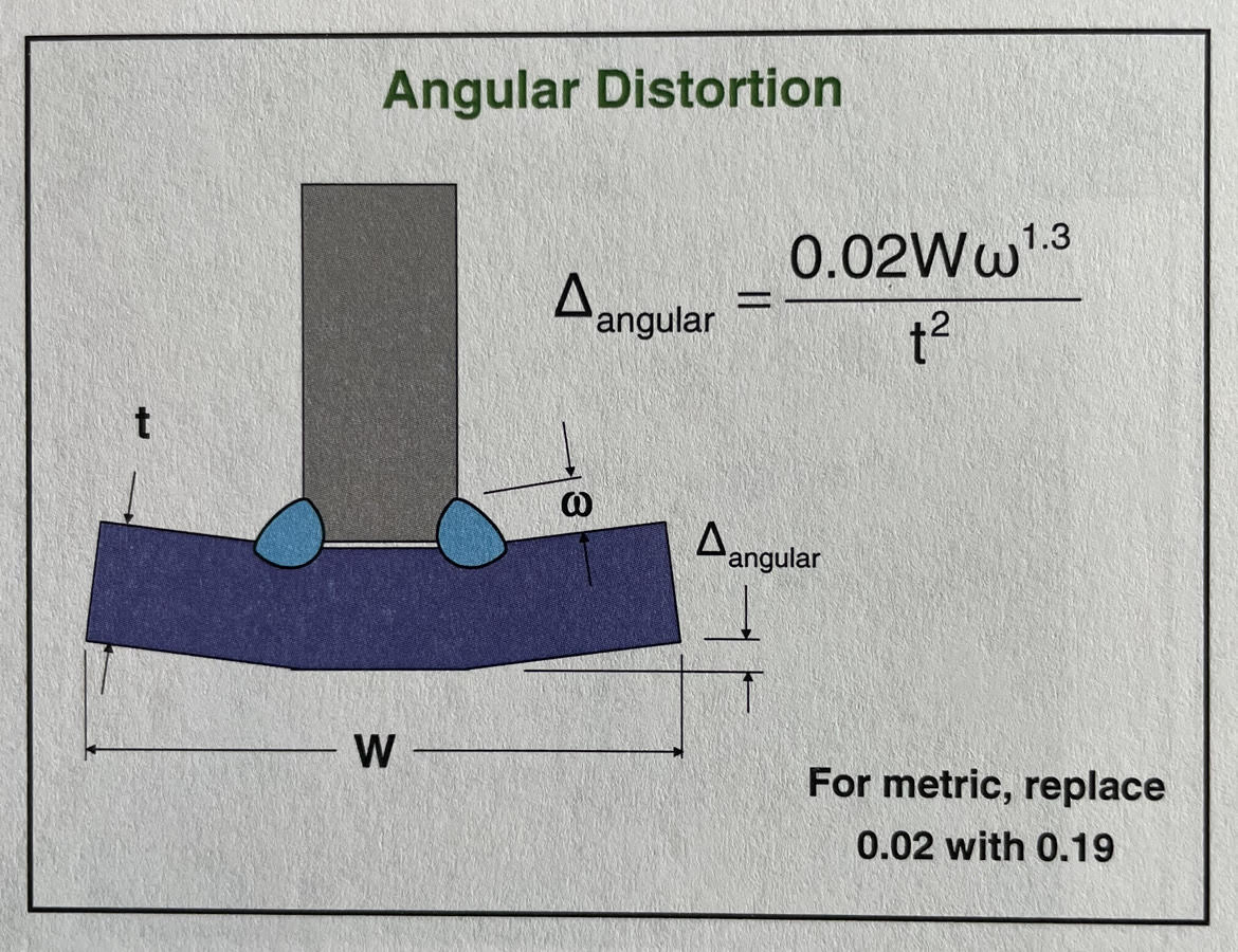
As you can see by this formula, if your fillet weld size increases so does the amount of distortion. If a welding drawing shows a welding symbol calling out a 3/16” fillet weld and the welder deposits a ¼” fillet weld they are increasing the amount of distortion. Sometimes a slight increase in leg size can put you over the dimensional tolerance limit and cause very expensive rework. It is highly recommended that weld sizes be called out on drawings and that welders are given the right tools and proper training in order to make welds of the correct size.
Excessively high heat input without preheat
If you look at the formula for angular distortion covered in Mistake 1 above, you’ll notice that heat input is not part of the formula. Nor are any of the components of the heat input formula which are amperage, voltage and travel speed.
If you look at other distortion formulas such as the ones for transverse shrinkage and longitudinal distortion you won’t find anything on heat input either. However, this does not mean heat input is not important. Weld size directly correlates to heat input. This means that the bigger the weld the higher the heat input For more information on this you can read The Relationship Between Heat Input and Weld Size.
However, if you’re adhering to the correct weld size, how can you lower the heat input? Here is where pulse welding can come into play, especially in GMAW (mig) welding. In pulsed spray transfer, the overall amperage is reduced compared to spray transfer without reducing the wire feed speed. This means that for a given weld size the heat input will be less using pulse welding.
Pulse essentially allows us to weld “colder” but still allows for proper penetration if set correctly. By reducing the overall amperage and heat input, the expansion and contraction of the weld nugget is not as severe, thus causing less distortion.
If you don’t have the ability to pulse weld, you can reduce distortion by preheating the parts before welding. This slows down the cooling rate and provides a more uniform heating and cooling of the weld, heat affected zone (HAZ) and adjacent base metal which in turn minimizes distortion. So, it’s not about the amount of heat we put into the weldment, but rather the impact of the heating and cooling cycle on the weld, HAZ and adjacent base metal.
Inadequate joint design
While the first two mistakes occur in the shop, this mistake takes place in the design stage. There are many ways in which different joint designs can affect distortion. But one of the most common ones is the specification of complete joint penetration (CJP) welds when partial joint penetration (PJP) welds would provide sufficient strength.
Now, why does this happen? Aren’t design engineers supposed to be very smart and have all the fancy tools and software available to ensure the best and most efficient design? Well, they do, but the problem lies in that they are not trained in two main areas: welding process and welding economics.
Here’s how this happens. A CJP weld will always be stronger than a PJP weld. So a design engineer may choose to specify CJP welds or all joints. They do this to play it safe, to not take any chances. The problem is that it significantly increases welding costs. It also increases the amount of weld (weld volume) which as we saw in Mistake 1 (overwelding) is a huge contributor to distortion.
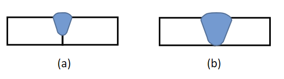
The figure above illustrates the effect of specifying a CJP weld (b) rather than a PJP (a). It is quite clear that the weld volume is significantly more in the CJP than the PJP. Thus, it will cause much more angular distortion.
It is very important that design engineers understand the impacts of specifying weld sizes and that bigger welds are not always better. Not only do they add to the cost of fabrication, but they can introduce other problems such as distortion. In materials like austenitic stainless steels it can cause more serious problems as is the case of sensitization.
There are many other mistakes that can lead to distortion, but in our experience the above three account for the majority of cases. Control these three and you’ll significantly reduce the amount of rework associated with distortion.
Are you having issues with distortion in your welding operations? If so, how are you addressing it? What did you find works best to mitigate this costly problem?
REFERENCE: Welding Procedure Development for Non Welding Engineers
AWS D1.1 Prequalified Welding Procedures:
332 Prequalified Welding Procedure Specifications for Steel Fabricators. Developed and reviewed by welding engineers and certified welding inspectors.