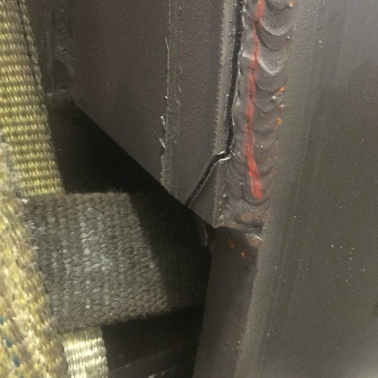
Not all weld discontinuities are weld defects, but all weld defects are discontinuities. Understanding the difference will let you know if you need to scrap a part, repair it or simply add more weld. There are many codes depending on what type of product you are welding on. The codes are used as guidelines by manufactures to write their own specifications. Just because a certain Code allows for a certain amount of porosity, a manufacturer may not allow its suppliers to have any.
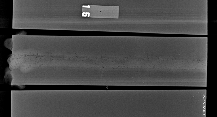
X-ray of an aluminum groove weld test. The surface showed no porosity. The dark spots are voids (porosity) and show up dark due to being lower density areas. Porosity is not always on the surface of the weld. Adequate gas shielding, clean base metal and proper welding procedure are necessary to avoid all porosity.
Most of the discontinuities in the list below can be detected visually. Visual inspection is the easiest and least expensive of all non-destructive inspection methods. The tools necessary to carry out visual inspection are few and not expensive. Tools such as rulers, weld gages and a magnifying glass are pretty much all you need. It is critical that weld inspection takes place before, during and after welding.
A weld discontinuity is a flaw in the weld. Discontinuities, as stated above, are not necessarily weld defects. They become weld defects when they exceed specified maximums of the code or customer specifications. This means that you can have weld discontinuities and still have an acceptable weld. However, we always want welds free of discontinuities whenever possible.
Below are 10 of the most common types of weld discontinuities. This is not a complete list of all possible discontinuities.
1. Porosity – Cavities in the weld caused by trapped gas during solidification of the weld metal. Common causes are lack of shielding gas, excessive arc length, or dirty base material. Another no so common cause can be arc blow, where magnetic fields cause an erratic arc. By codes or manufacturer specs porosity may be present but each individual hole should not exceed a certain length and the total length of all holes cannot exceed a certain value per inch of weld.
2. Lack of Fusion – Also called lack of penetration or cold lap. Lack of fusion refers to the base material not being fused properly to the other piece or weld metal itself. This is caused by having welding parameters that are too low. Although this cannot be detected, at least not easily, after welding, the welder himself can see this while welding. A trained welder is able to recognize if the arc is digging properly into the base material.
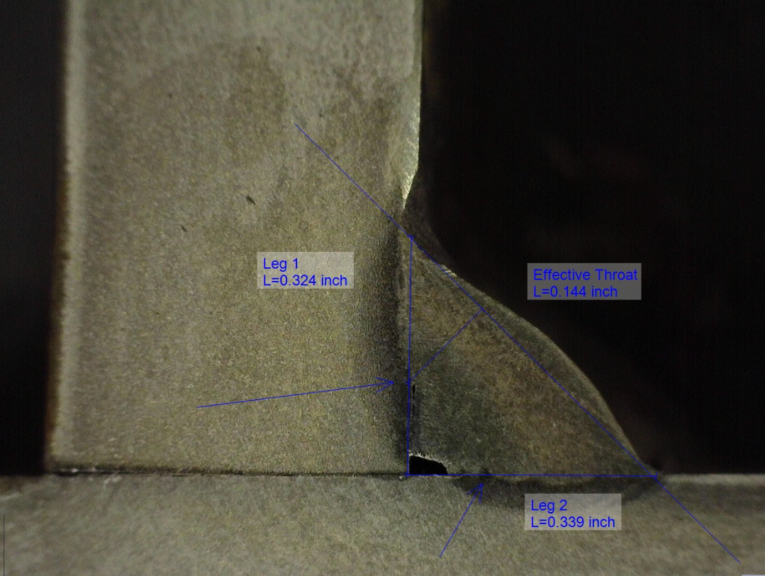
Lack of fusion cannot be detected visually. The image above shows a macroetch of a fillet weld showing that lack of root fusion.
3. Undercut – This is a grove that appears at one of both toes of the weld. This is caused by lack of fill. The lack of fill can be due to excessive voltage or too low wire feed speed. Can also be caused by incorrect welding technique. As with porosity, some undercut may be acceptable.

Undercut creates a mechanical notch which acts a stress riser. It also reduces the effective area of the base metal. The image above also shows overlap (bottom weld toe).
4. Incorrect Bead Placement – As the name states, this discontinuity occurs when the weld bead is not in the right location. It can mean missing the joint completely or not having equal legs in a fillet weld. Incorrect bead placement can be a weld defect if the root is missed or if the smallest leg size does not meet the specification minimum.
5. Spatter – This are small drops of weld metal that escape the arc and land on the adjacent base material fusing themselves to it. Spatter is not a weld defect, but again the maximum allowable is per the customer’s specification. Spatter is caused by incorrect welding procedures, including amps, volts, welding speed, travel and work angles, and even shielding gas.
For more on spatter read: 7 Causes of Welding Spatter and How to Eliminate It
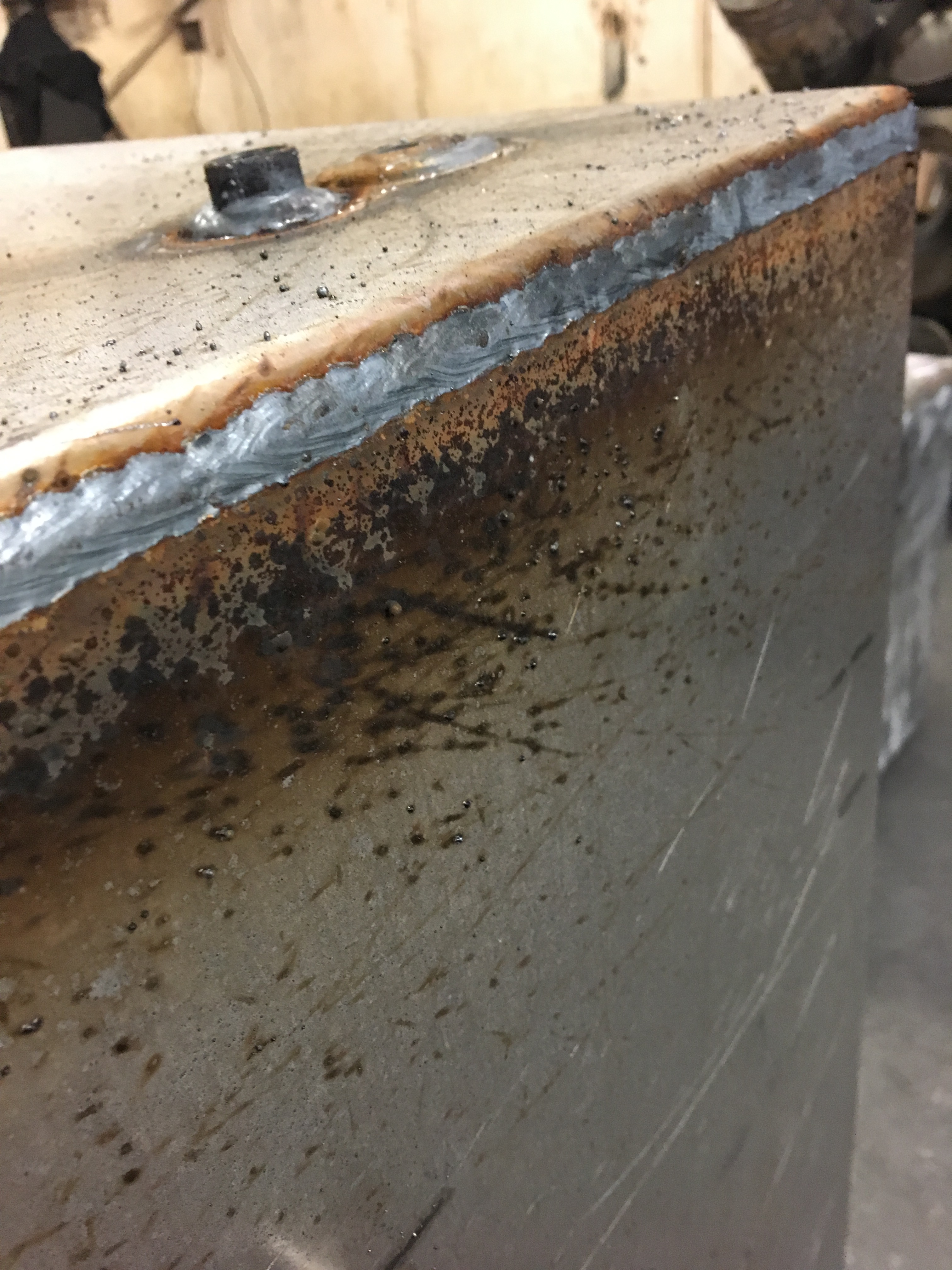
Spatter does not affect the structural integrity of a weld in most cases, but it almost always has to be removed adding to total cost.
6. Incorrect Weld Size – This can be either a weld that is too big or too small. Although big welds are preferred over small welds it is still detrimental at times to have a big weld due to excessive heat input, weld stresses and distortion. Weld size is affected by travel speed and welding procedures, specifically wire feed speed. It can be easily measured by the use of weld gages.
7. Slag Inclusions – This consists of slag trapped between passes. This is impossible to detect via weld inspection after welding is complete and very hard to detect while welding. Causes are inadequate cleaning of weld surface between passes. It can also occur in single pass welds when slag gets trapped in the root and toes of the weld.
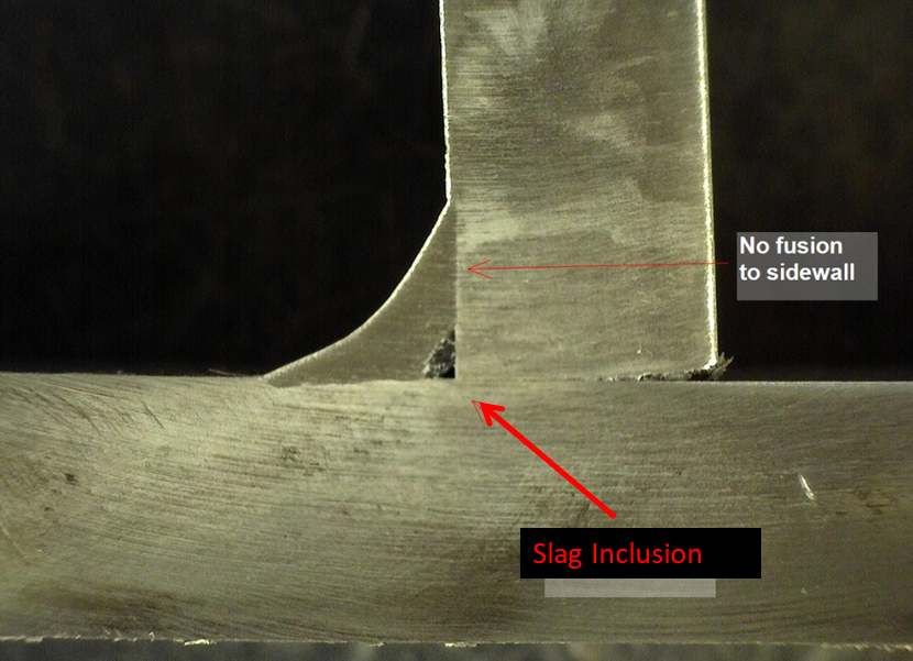
Welding processes such as SMAW and FCAW are susceptible to slag inclusions. Slag inclusions prevent proper fusion and can have sharp ends which creates a crack-like behavior.
8. Excessive Reinforcement – This is a weld that is too big or has too much convexity (too much build up). Usually caused by low travel speeds or incorrect procedures.
9. Melt Through – This occurs when welding procedures and/or technique provide too much penetration and metal comes out of the back of the joint.
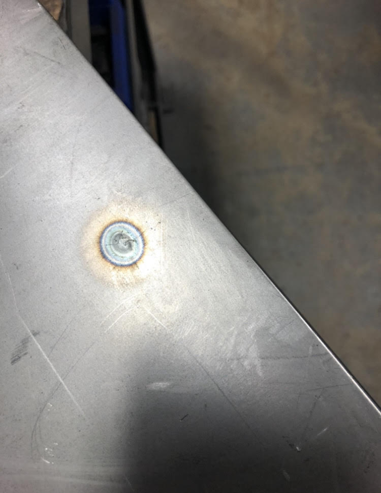
Melt-through from a tack weld on thin gauge material. This is not just a heat mark, there is metal that is protruding from the surface of the base metal.
10. Cracks – Cracks are the most detrimental discontinuity for the integrity of a welded connection. Cracks, in any amount, will constitute a defect with very few exceptions. Cracks due to stress relieving of hardfacing welds is one of these exceptions. Cracks have sharp ends which allows them to grow, in some cases very quickly. For further explanation you can read Understanding Why Welds Crack.
It will be welding codes, standards and specifications that determine the amount allowed, if any, of the above described discontinuities. Codes are concerned with the structural integrity of welds, no so much with aesthetics. So some fabricators will have internal quality standards that do not allow any amount of spatter or which will reduce the allowable amounts of other discontinuities. The acceptance criteria of welding codes should be used as a bare minimum.
References:
Fabricators’ and Erectors’ Guide to Steel Welded Construction

Writing my level 1 inspector, I find that measuring correct is not defined, are craters measured and if so- how. Are all discontinuities measured, if so where does a person locate information? Thanks
Hello Rod, craters are not desirable simply because they reduce the effective lenght of the weld. Since the desired throat dimension is not achieved in a crater, the portion of the weld that is a crater does not count toward the overal lenght of the weld. If you have a print calling for a specific weld lenght the crater will not count towards that lenght. You can find information on this in AWS D1.1 Structural Welding Code, it states that “all craters shall be filled to provide the specified weld size,exceptfor the ends of intermittent fillet welds outside of their effective length.” This means that if you have intermittent welds of 2 inches in lenght you can have a crater, but it must be outside of the 2-inch length.
As far acceptance criteria in regards to the total sum of the length of all discontinuities that will depend on the code or standard your are following. This information will be in the code book of the specified standard (i.e AWS D1.1, AWS D1.6, ASME Sec IX, API 1104, etc.). On AWS codes look under the Inspection clause.
Thank you