
Developing, or writing a welding procedure, goes far beyond setting up amps and volts. It entails the selection of many variables which fall under the 9 required components of welding procedure specifications we discussed last week. Today we look at those 9 components again, but rather than just stating what they contain we explain how your selection of values for these components impact quality and productivity.
Developing welding procedures is normally the responsibility of the welding engineer. However, a large number of fabricators do not have a welding engineer on staff. So, this responsibility can fall in the hands of other engineers, quality control personnel, production managers, welding leaders, welders or others. This is not a problem provided that the person that ends up developing the WPS has a very good understanding of the welding process being used and of the effects of the welding variables that comprise a WPS.
Unfortunately, many times the people that end up determining welding parameters don’t have the knowledge or understanding necessary to do so. We spend a lot of time teaching our consulting clients exactly this, how to select the right parameters when developing a welding procedure. And if you have been with us for a while you also know this is why we created Welding Procedure Development for Non-Welding Engineers.
The step-by-step process taught in this guide aims at helping the user not just understand the many variables that go into a WPS, but also some of the basic fundamentals of joint design, distortion, welding metallurgy, weld quality and welding productivity.
The key to developing a WPS is to understand how the many variables impact quality and productivity. It is fundamental to understand the acceptance criteria we are trying to meet. The acceptance criteria can be found in codes, standards or other contract documents and can include items such as weld size, weld length, depth of penetration, amount of reinforcement, allowances for certain discontinuities, geometry of the toes, etc.
Once you understand the acceptance criteria you can start developing your welding procedure. Selection of the base material typically is the responsibility of the design engineer, but beyond that, the welding engineer, or other person in charge of writing the WPS, has a wide range of options when it comes to the many essential variables.
Many welding processes may be used. Below we explain why selecting each of these variables is extremely important.
- Joint Design – although this may be the responsibility of the design engineer, it is sometimes left up to the welding engineer. Selecting a joint design and dimensions has a significant effect on quality, productivity and cost. Using prequalified joints may save you money by not having to do qualification tests, but a better joint design (that requires testing) may prove to be the best option.
- Base Metals – these are typically selected during the design phase and are not part of procedure development. However, we must have a good understanding of the metallurgical implication of welding different base metals. Some, such as medium to high carbon steels, may be susceptible to hydrogen induced cracking. So we’ll need to be extra careful in determining preheat and interpass temperatures as well as selecting a low hydrogen process. Other base metals, such as austenitic stainless steels, are susceptible to sensitization, so instead of desiring a slow cooling rate we want the exact opposite.
- Filler Metals – the selection of filler metal is very important. It is not always advisable to to match the filler metal to the strength of the base material. This is typically only necessary in complete joint penetration welds, so consider undermatching filler metals.
- Welding Position – we almost always want to weld in position (flat or horizontal for fillet welds and flat for groove welds) if at all possible. Positioning the part may require equipment that is not available so welding out-of-position is sometimes necessary.

Welding position are designed by numbers 1 through 6. The image above show positions for groove welds. Numbers 5 and 6 are for groove welds on pipe. - Preheat and Interpass Temperature – these temperatures are determined in order to achieve the desired cooling rate. It is key to specify the right temperatures as this will prevent cracking in susceptible materials.
- Post Weld Heat Treatment – this may be needed to regain dimension tolerance, to prevent cracking, to reduce residual stress or to regain certain mechanical properties. 6.
- Shielding Gas – if using a welding process that involves shielding gas it is important to follow the recommendation of the filler metal manufacturer. In some cases you can use many different gases. If this is the case, you must choose the one that is best for the application. Some shielding gases perform better on mill scale than others. Other gases are better on clean material and fast travel speeds. If you are using the submerged arc welding process the flux will provide the shielding. It will also have a huge bearing on mechanical properties as the alloys in the flux will be added to the weld metal.

One of the effects of changing shielding gases can be seen in penetration profile. High argon mixtures provide deep pointed penetration while high CO2 mixes exhibit a more rounded penetration profile. - Electrical Characteristics – these are usually determined by the process being used. GMAW and gas shielded FCAW will use direct current electrode positive (DCEP or DC+). GTAW and self-shielded will use direct current electrode negative (DCEN or DC-). Some GTAW applications require alternating current (AC). Stick welding (SMAW) can be done with DC+, DC- and AC, it all depends on the application and the filler metal being used.
- Welding Variables – selecting the right amperage, voltage and travel speed is essential. These variables have a significant impact on quality and productivity. It is important to understand that a welding procedure may achieve the desired quality, but have very low productivity. Just because you meet the acceptance criteria it doesn’t mean you have an optimal welding procedure. For a look at how the selection of these variables can impact quality read 7 Variables That Affect Weld Penetration. Penetration is not the only thing to consider, but it certainly is one of the most important.

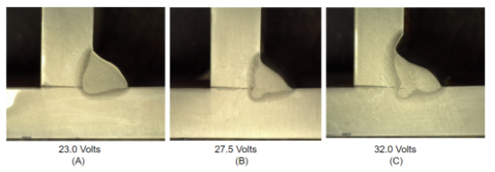
Effects of changing voltage from 23 to 32 volts when running an 0.045″ ER70S-6 GMAW electrode at 400 ipm (290 amps) with a 90% Argon/10% Carbon Dioxide shielding gas. As voltage increases so does arc length. This widens the bead. Excessively high voltage can lead to undercut as seen on (C) above. - Welding Process – many times the welding process selected is the one that is already in use in the shop. This is not always the best option as certain processes are better suited for certain applications. Selecting a different process may necessitate the purchase of new equipment, but potential efficiency gains may prove this to be a good investment. An example is selecting flux-cored arc welding over gas metal arc (mig). The flux-core process is less efficient because of the generation of slag and the need to remove it. However, if there is a lot of out-of-position welding, flux-core may provide higher deposition rates and be the best alternative.

Next week we’ll discuss how to verify (qualify) that our selection of the above parameters can produce sound welds. Although qualification by testing is not always necessary, it is important to understand what types of tests are used so that you can verify your procedures.
Reference: Welding Procedure Development for Non-Welding Engineers.