Unless you are a design engineer you typically don’t have to worry about determining the strength of a weld. The strength of a weld refers to its load carrying capacity, or how much load it can handle before it fails. However, it is very important for all of us involved in the welding process, from welders to production supervisors to quality personnel and welding engineers to understand the basics of weld design.
Overwelding is an epidemic in our industry. This stems from not really understanding how to properly size a weld. But even companies with teams of engineers, having the luxury of using finite element analysis software, still call for weld sizes much bigger than necessary. This overwelding can have a tremendous impact on cost. To get an idea of how much you can read: Cost of Overwelding.
Having a basic understanding of how to properly size welds will equip you to question the size of certain welds. We are not telling you to go out and reduce all weld sizes immediately. Any change of this magnitude must be reviewed and approved by engineering. However, the savings can be significant.
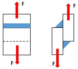
To explain how to determine the strength of a weld we will use a simple example. In this article we will discuss only how to determine the strength of a transverse fillet weld. A transverse fillet weld is one that is perpendicular to the force applied as seen in the image below.
Because the load is perpendicular to the weld it is considered a tensile load. The formula we need to use to determine the load carrying capacity of the weld is:
Where
σt is the tensile strength of the weld (determined by the filler metal being used) in PSI
F is the force the weld can handle, in other words, the strength of the weld in lbf
A is the effective area of the weld
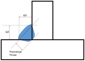
The effective area of a weld is calculated by multiplying the length of the weld times the throat of the weld. For design purposes we use the theoretical throat as shown below.
In the above diagram, “w” is the fillet weld leg size. The theoretical throat is calculated by multiplying “w” times the cosine of 45˚ which is 0.707. For all fillet welds with both legs being of the same size, the theoretical throat will be 0.707 x “w”.
If the weld is 20 inches in length then the effective area will be 20 x 0.707 x “w” .
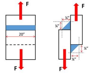
Keeping with our example, there are two welds joining the two members. Both welds have a leg size of ¼-in and are 20 inches in length. We want to determine the maximum load these welds can withstand. The welding is being done with an ER70S-6 GMAW wire with minimum tensile strength of 70,000 psi.
First, determine the throat size.
Throat = “w” x cos 45˚ = (1/4) x (0.707) = 0.177”
Now determine the effective area of the weld. Remember, there are two 20-inch long welds.
Effective Area = 2 x length x throat = (2) x (20) x (0.177) = 7.08 sq-in
Now we go back to our main formula.
Because we are using an ER70S-6 wire, is equal to 70,000 psi. Now we have all the values except for the one we are solving for, F.
We rearrange the formula to solve for F.
F = (70,000) x (7.08) = 495,600 lbf
So our 20-inch long, double-sided, ¼” fillet welds have a load carrying capacity able to withstand a tensile force of almost half a million pounds. To put this in perspective, a Boeing 747-400 weighs roughly 404,600 pounds. So, our seemingly tiny welds can pick up a 747! That is pretty impressive. However, before you go to the airport and put this to the test there are a few things you should know.
- If the force is applied rapidly the weld would fail at a significantly lower load
- If the force is not applied perfectly evenly along both welds the welds would fail at a significantly lower load
- If there are any weld discontinuities such as cracks, craters on undercut, the welds would fail at a significantly lower load
- If the load is not perfectly static, the welds would fail at a significantly lower load
- If the load is not perfectly perpendicular to the welds, the welds would fail at a significantly lower load
The list of “ifs” keeps going. Because of this, welding codes introduce a factor of safety. Factors of safety are used to make sure we don’t overload structures. In our next post we’ll provide an example of fillet welds loaded in shear. This is basically the worst case scenario and limits the maximum force that can be applied to a weld before it fails. Most of the design is made with the assumption that fillet welds will be loaded in shear.
A word of caution: the above calculations are used to explain the theory behind weld design. It is a simplified example to illustrate certain design principles. Proper testing and approvals by engineering must be in place before any changes can be made to welds when a specific size has previously been determined.
Reference: Design of Welded Structures


The throat area, A, is half of a square, right? So, if the side of the square is w, then:
A = 1/2 x w x w
… not 0.707 x w.
Am I missing something?
Please disregard my question above – I re-read your description and now it makes perfect sense. The weld surface area, A, being considered is the throat depth (= 0.707 x w) times the weld length.
Feel free to delete my email trail so it doesn’t unduly confuse anyone.
Thank you for this very good description and simple hand calculations.
FCAW X section calculation for determining number of passes to estimate time for time disputes. For eg 48 in pipe pile splice using 5/64 ” FCAW. (Understanding up front that puddle widths very between welders) 1.5 inch gap and 1.25 inch pile thickness for roughly a cross section area of 1.88 square inch .
Excuse me, but I believe this article needs a bit more clarification. “In the above diagram, is the fillet weld leg size. The theoretical throat is calculated by multiplying times the cosine of 45˚ which is 0.707.” Is there a variable missing between the words ‘multiplying’ and ‘times’ or am I missing something?
Yes, the leg (w) size is multiplied by the cosine of 45 (0.707) to get the theoretical throat. The leg size is indicated by the greek letter omega (looks like a “w”). This greek character was not coming up on the page and this is why there was nothing in this place you indicated. We have edited the post to show “w” instead of the greek character.
How do you determine the size of welds when you have complex structures?
Some structures get too complex to do this by hand. Finite Element Analysis (FEA) software can be used. However, the output of the FEA software is only as good as the data you feed it.
SIr,
Am I missing something? Aren’t these welds loaded in shear, which shear strength is lower than tensile strength? Thank you in advance for your reply.
Hi Dennis,
It is almost impossible to load a fillet weld in pure tension when it is part of a structure. The post is for educational purposes only . The weld is loaded in tension (as close to pure tension as possible). The load is applied transverse to the direction of the weld. For design purposes it is common practice to use the shear strength calculations on shown on: https://weldinganswers.com/how-to-determine-the-shear-strength-of-a-fillet-weld/
Depending on the direction of loading some codes, such as AWS D1.1, will allow for a higher multiplier (0.30 x EXX is used for shear) and thus a higher allowable stress.
About the speed of loading. Mechanical engineer mat have learn that: we have a dynamic stress multiplier factor.
Ks = 2 if the load is applied quickly. So, the load to broke a weld is half of the one compute in your blog. And it can be less if we have a gap between the hook (or the loading device) . For exemple, for a sling with a 6 inches drop… we have Ks (theorical) of 30!
Référence: aide-mémoire de la résistance des matériaux, Pisarenko, Mir edition. Sorry it’s in french.
Thanks so much for sharing Yves!